WATER
Direct Reading Fire Service (DRFS) Meters and Compact Fire Service (CFS) Meters are for installations where UL or FM requirements must be satisfied. They meet a variety of requirements for fire service ratings, flow demands and applications or where limited installation space is a factor.
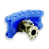
The Model W-3500 CFS or DRFS Turbo Meter with Strainer is based on the turbine principle of measurement; its operating range is from 35 to 3500 gallons per minute (8 to 795 m3/h) with registration accuracy of 100% ± 1.5% of actual throughput. The Model W-5500 CFS or DRFS Turbo Meter with Strainer operating range is from 55 to 5500 gallons per minute (12.5 to 1250 m3/h) with registration accuracy of 100% ± 1.5% of actual throughput.
Conformance To Standards: Sensus Compact Fire Service Turbo Meters comply with ANSI/AWWA Standard C703 (most recent revision). Each assembly is performance tested to insure compliance.
Performance
The meter is intended for use where measurement of fire service water usage is desired. The meter and strainer are Approved by Factory Mutual and Listed by Underwriter’s Laboratories, Inc. for use on domestic services as well as fire service connections to public water supplies. Applications should be where moderate to heavy flow demands are anticipated in addition to providing fire protection service capability. The meter and strainer are pressure tested, calibrated and accuracy tested before shipment. No additional adjustments are required by field personnel.
Construction
The meter consists of two basic assemblies—the maincase and the measuring chamber. Straightening vanes in the maincase minimize the swirl upstream of the meter so as to direct the flow evenly to the rotor. The measuring chamber assembly includes the rotor, adjusting vane (for calibration) and sealed Direct Reading (DR) register.
Magnetic Drive
The Right Angle Magnetic Drive eliminates conventional worm or miter gears normally required for horizontally mounted rotors or turbine measuring elements. Registration is accomplished by combining the magnetic actions of a driver magnet (embedded in the rear face of the rotor), a three-legged flux carrier and a cylindrical follower magnet attached to the gear train shaft inside the register’s magnet well. Water flowing through the meter causes the rotor (with magnet) to turn, as one of the magnet poles passes one ofthe flux carrier legs, the magnetic force is transmitted through the flux carrier leg to the follower magnet, causing the register shaft to rotate.The only moving part in water is the rotor assembly.
Rotor
The thermoplastic rotor with ceramic bearing rotates on a ceramic sleeved stainless steel shaft.The rotor assembly is virtually weightless in water, thus adding to bearing life.
Maintenance
The measuring chamber can be removed, repaired and/or replaced without disturbing the maincase in the line. A spare chamber can be utilized in the event maintenance is required. Cover plates are also available to keep the line in service while the measuring chamber is repaired and recalibrated. Factory testing, repair and measuring chamber exchange programs are available.
Strainer
Meters are furnished with Factory Mutual Approved and U.L. Listed Sensus CFS or FS Strainer which must be installed immediately upstream of the meter. Two drain plugs are provided to flush the screen under pressure. The CFS strainer contains a “V” shaped screen with four times the equivalent open area of a 8” (200mm) pipe. Three 3/4” threaded holes are provided on the cover plate to assist in cover removal only.
